 EN

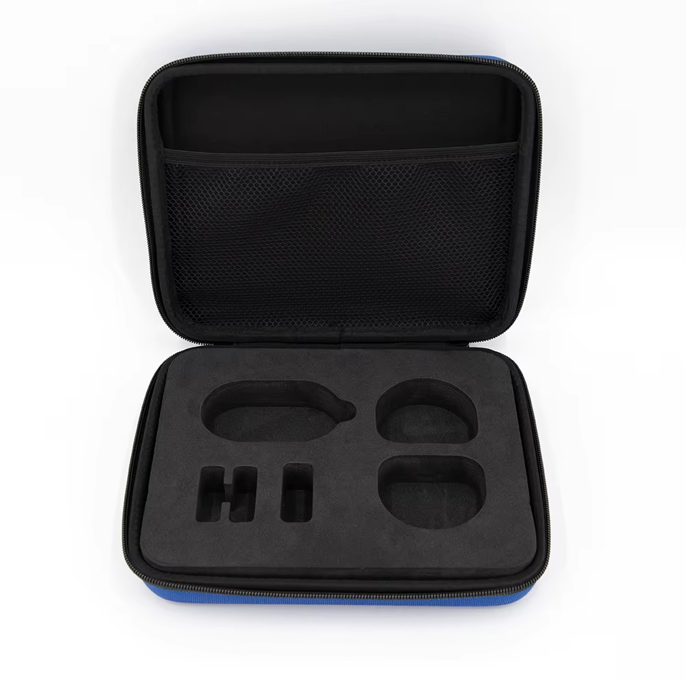
Shock Absorption Dynamics: How Precision Foam Cases Dissipate Impact Energy and Protect Sensitive Payloads
In high-reliability packaging, protecting fragile electronics, medical diagnostics, tactical gear, and optical systems requires managing dynamic mechanical forces. When a protective case experiences a drop, shock, or vibration during transit, the payload inside experiences rapid acceleration. Without proper mitigation, this force translates directly into component displacement, structural fatigue, or immediate calibration failure.
Understanding how specialized foam formulations convert kinetic energy into harmless thermal dissipation is critical for packaging engineers, procurement managers, and logistics planners.
For a comprehensive guide covering custom enclosure architectures, material selection, and global supply chain strategies, visit our primary
The Physics of Shock Absorption: Compression, Hysteresis, and Recovery
When a foam-lined protective case impacts a hard surface, the internal cushioning acts as a non-linear spring-damper system. The mechanical energy transfer follows a defined thermodynamic and physical progression:
-
Cellular Wall Compression: Upon initial shock, the open or closed cellular matrices within the polymer compress. As fluid (air or gas trapped within the cells) compresses and cell walls flex or buckle, the impact energy is distributed across a wider surface area.
-
Viscoelastic Energy Conversion: Polymer foams exhibit viscoelastic behavior, combining viscous fluid resistance with elastic solid behavior. A portion of the impact energy is temporarily stored elastically, but a significant fraction is converted into heat via internal molecular friction. This ratio of energy dissipated versus energy stored is known as hysteresis.
-
Deceleration Smoothing: By extending the time duration over which velocity drops to zero, the foam flattens the acceleration spike. A sharp 300 G impact over 2 milliseconds is converted into a manageable 30 G load spread over 20 milliseconds, reducing transmitted peak force by up to 70%.
-
Thickness Recovery & Compression Set: Following impact, the foam must return to its original thickness to protect against secondary shocks. Low compression set percentage (measured via ASTM D3575) ensures the material maintains its cushioning clearance throughout multi-drop shipping sequences.
Material Comparison: EPE vs. XLPE vs. EPP Performance Profiles
Selecting the correct polymer foam involves balancing volume energy absorption, density, compression set resistance, and cost. Below is a comparative breakdown of the three primary closed-cell cushioning foams used in technical packaging:
| Material Property | Expanded Polyethylene (EPE) | Cross-Linked Polyethylene (XLPE) | Expanded Polypropylene (EPP) |
| Density Range | 20 – 60 kg/m³ | 25 – 200 kg/m³ | 15 – 120 kg/m³ |
| Relative Energy Absorption | Moderate | High | Very High |
| Compression Set (%) | 30% – 40% | 5% – 15% | 3% – 8% |
| Rebound Memory / Reusability | Low (Single-trip) | Moderate to High | Exceptional (Multi-trip) |
| Surface Finish & Aesthetics | Coarse, fibrous | Smooth, fine-cell, non-abrasive | Molded bead, clean |
| Cost Index | Low | Medium | High |
Real-World Drop Test Benchmarks (ASTM D4169 / ASTM D5276)
In a standardized 1.2-meter drop test supporting a 5 kg payload:
-
EPE (30 kg/m³): Transmits approximately 75 G of peak acceleration to the payload. Higher compression set leads to progressive bottoming-out after repeated drops.
-
XLPE (45 kg/m³): Limits peak force to 40 G. Excellent non-abrasive surface quality protects delicate anodized or coated device housings.
-
EPP (60 kg/m³): Limits peak force to just 25 G. Retains over 95% of original thickness even after 10 consecutive drops on the same face, making it the industry standard for returnable transit cases and reusable military containers.
Payload Immobilization: Precision CNC and Die-Cut Fabrication
Even high-performance foam fails if the internal payload moves freely within the enclosure. Internal clearance allows the payload to gain momentum relative to the case, resulting in point-impact shock when the payload hits the inner wall.
Custom immobilization eliminates motion across all six degrees of freedom (surge, sway, heave, roll, pitch, and yaw).
CNC Routing vs. Steel-Rule Die-Cutting
To achieve total zero-clearance encapsulation, custom foam inserts are manufactured using precise digital manufacturing workflows:
-
3D Laser Scanning & CAD Modeling: Physical devices are scanned to create accurate CAD geometries, accounting for buttons, optical lenses, cable stress reliefs, and uneven mass distribution.
-
Precision CNC Milling: Uses high-speed rotating cutters to route complex, multi-depth cavities into high-density XLPE or EVA foam. Achieves tight dimensional tolerances within ±0.5 mm, creating a custom contour fit for low-volume, high-value medical instruments or military gear.
-
Steel-Rule Die-Cutting: Presses custom steel blades through foam sheets. Ideal for high-volume production runs, producing clean, uniform cutouts with high repeatability.
By replacing loose-fill packing, bubble wrap, or generic egg-crate foam with custom-molded inserts, the payload becomes an integrated structural component of the overall packaging system.
Case Study: Reducing Medical Device Transit Damage from 9.2% to 0.4%
A manufacturer of portable ultrasound imaging stations experienced severe product field failures during global distribution.
The Challenge
-
Historical Failure Rate: 9.2% across ground and air logistics channels.
-
Primary Failure Modes: Optical alignment drift, loose internal connectors, and cracked casing corner mounts caused by low-frequency road vibration and handling drops.
-
Legacy Packaging: Generic off-the-shelf outer case lined with non-custom open-cell PU egg-crate foam padding.
The Engineered Solution
Engineers redesigned the internal packaging into a custom multi-density isolation system using a rigid outer shell lined with custom CNC-routed XLPE foam:
-
Isolated Cavities: Independent cavities were milled for the main display unit, transducer probes, power supply, and spare battery modules.
-
Resonance Control: Density was varied across support zones (65 kg/m³ under heavy chassis bases; 30 kg/m³ around sensitive probe heads) to shift the natural resonance frequency away from standard transport frequencies (10–30 Hz).
-
Total Axis Immobilization: Zero-clearance side walls prevented transverse shifting during air freight turbulence.
Verified Results
-
Damage Reduction: Annual shipment damage plummeted from 9.2% down to 0.4% (a 95.7% overall reduction).
-
Financial Impact: Eliminated costly field recalibration visits, reduced warranty reserve allocation, and improved customer confidence across international delivery channels.
5. Vibration Damping and Technical Standards Validation
Managing Resonance with Open-Cell PU and Neoprene
While closed-cell foams (XLPE, EPP) handle drop impacts, lower-frequency transport vibration (such as diesel engine idle or cargo plane vibration) requires soft damping materials:
-
Open-Cell Polyurethane (PU): High air-permeability provides strong damping characteristics, absorbing low-amplitude vibrational energy and converting it to thermal dissipation at frequencies between 15 Hz and 50 Hz.
-
Neoprene Rubber Pads: Placed at load-bearing points under heavy equipment to isolate low-frequency harmonic hum and prevent structural fatigue.
Industry Test Protocols (ASTM D4169 & MIL-STD-810H)
Validating a protective foam enclosure requires rigorous laboratory testing:
-
ASTM D4169 (Distribution Cycle 13): Simulates air and truck transport, subjecting the complete enclosure to random vibration schedules (0.52 G rms) and consecutive drop sequences.
-
MIL-STD-810H (Method 514.8 & 516.8): Verifies packaging performance under extreme transportation vibration profiles and transit drop tests from heights up to 1.8 meters.
Technical Performance Baseline
To guide design specs for technical foam packaging, refer to these standard operational metrics:
| Property | Standard Test Method | Target Performance Metric |
| Static Loading Range | ASTM D3575 | 0.02 - 0.15 MPa (Matched to foam density) |
| Peak Transmitted Acceleration (1.2m drop) | ASTM D4169 / D5276 | < 35 G (For delicate electronics) |
| Water Absorption (by volume) | ASTM D1056 | < 0.1% (Closed-cell requirement) |
| Thermal Operating Range | Internal Protocol | -40°C to +80°C |
By combining precise polymer density selection with custom-milled internal geometry and certified drop testing, custom foam cases provide long-term, repeatable protection for critical equipment. To review advanced thermoforming techniques, outer shell options, and custom engineering parameters, explore our main
Table of Contents
- Shock Absorption Dynamics: How Precision Foam Cases Dissipate Impact Energy and Protect Sensitive Payloads
- The Physics of Shock Absorption: Compression, Hysteresis, and Recovery
- Material Comparison: EPE vs. XLPE vs. EPP Performance Profiles
- Payload Immobilization: Precision CNC and Die-Cut Fabrication
- Case Study: Reducing Medical Device Transit Damage from 9.2% to 0.4%
- 5. Vibration Damping and Technical Standards Validation
- Technical Performance Baseline
